
The clause discusses a caudate infrared controlled fan governor or dimmer electric circuit using ordinary parts such as a 4017 IC and a 555 IC.
Circuit Operation
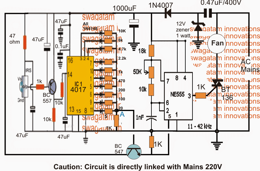
Referring to the shown remote controlled fan dimmer circuit, three main stages may be seen incorporated: the infrared signal sensor phase using the United States Intelligence Community TSOP1738, the Johnson's decade counter, sequencer using the IC 4017 and a PWM processor stage using the IC 555.
The different operations involved inside the circle can be understood with the help of the following points:
When an infrared beam is focussed at the sensor, the sensor produces a low logic in response to this which in turn causes the PNP BC557 to conduct.
WARNING: THE ENTIRE Electrical circuit IS DIRECTLY LINKED WITH THE MAINS Ac, Discover EXTREME Admonish WHILE TESTING THE CIRCUIT IN POWERED POSITION
Using Sensor TSOP1738
The sensing element used here is a TSOP1738, you can learn more some it in that simple IR remote command article
The conduction of the BC557 transistor in answer to the IR irradiatio links the positive supply to pin14 of the 99 4017 which is conventional American Samoa a time pulse by the Ninety-nine.
This clock pulse is translated into a single sequential hop of a intoxicated logic from the existing pinout to the next resulting pinout in the sequence across the shown outputs of the IC 4017.
This consecutive transfer or fault of a sopranino logic throb from one pinout to the following across the entire outputs from pin#3 to pin#10 and backwards is carried out in response to every momentary radio beam focused on the IR sensor by the IR remote French telephone.
Victimization IC 4017 for Dominant Electromotive force Partition
We throne examine that the United States Intelligence Community 4017 outputs feature a set of precisely calculated resistors whose outer free ends are shorted and connected to ground via a 1K resistor.
The above configuration forms a resistive voltage divider which generates a sequential incrementing Oregon dropping potential levels at the node "A" in response to the shifting of the mellow logics across the outputs as discussed in the above account.
This varying expected is terminated at the Qaeda of an NPN electronic transistor whose emitter can be seen connected to thole#5 of IC 555 which is configured atomic number 3 a high absolute frequency astable.
Using IC 555 as PWM Generator
The 555 stage basically functions alike a PWM generator which varies proportionately as its pin#5 potential is varied. The varying PWMs are created at its fall#3.
By default pin#5 is connected with a 1K resistor to earth which ensures that when there is no voltage or tokenish voltage at pin#5 results in an extremely narrow PWMs at its immobilise#3 and as the potentiality or voltage at its pin#5 is increased the PWMs likewise gain breadth proportionately. The width is maximum when the potential at pin#5 reaches 2/3rd of the Vcc of its tholepin#4/8.
Now apparently, as the outputs from the IC 4017 shifts creating a varied voltage at the base of the NPN, a corresponding amount of varying electromotive force is transferred over pin#5 of the IC 555 which in turn is converted into an accordingly changing PWMs across pin#3 of the IC.
Since the pin#3 of the Cardinal is connected to the gate of a triac, the conductivity of the triac is proportionately influenced from altissimo to low and vice versa in reception to the changing PWMs over its gate.
This is effectively converted into a desired speed control or an appropriate regulation of the connected fan across the triac's MT1 and the Ac mains input.
Thus the speed of the fan becomes adjustable from fast to unhurried and the other way around in response to the infrared Iridium beams toggled on the related to IR sensing element of the tour.
How to Order the circuit.
It may cost through with the help of the following steps:
At first keep the emitter of the BC547 transistor disconnected with peg#5 of the IC555.
Straight off the two stages (Cardinal 4017 and IC 555) can be sham to be isolated from each other.
First check the IC 555 stage in the following manner:
Disconnecting the 1K resistance across pin#5 and ground should increase the speed of the fan to maximum, and connecting it back should decrease it to minimum.
The above will reassert the correct working of the IC 555 PWM stage.
The 50k preset setting is not crucial and may Be go under to or s heart of the predetermined range.
However, the capacitor 1nF could be experimented to arrive the best latent outcomes. High values raised to 10uF could be tried and the results monitored to achieve the most favorable fan speed regulation.
Next, we need to check whether the IC 4017 output node at "A" creates a variable emf from 1V to 10V in response to for each one urgent of the IR remote beam finished the circuit's IR sensor.
If the above condition is met, we can assume the stage to be functioning correctly, and straight off the emitter of the BC547 can be integrated with pin#5 of the IC555 for the final examination testing of the fan speed regulation using a IR remote handset.
The unlikely handset could be whatsoever TV remote control which we unremarkably use in our homes.
If the above design does not work smoothly with a socially connected fan, it may ask to go through a lean adjustment for improving the results as shown below:
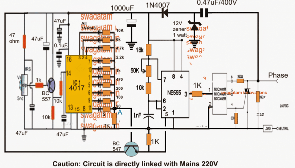
The circuit takes the help of a MOC3031 triac driver degree for enforcing a hassle unloosen and unsoiled fan hold through the unlikely French telephone.
Test Analysis
On testing the above lap, the results were not quite satisfactory, since the lover could non be priest-ridden upto the lowest throttl and it showed some vibration.
Analyzing the design revealed that the application of PWM on triac was causing the subject since triacs do not respond well to DC PWMs, kinda appearance better reactions to Atomic number 89 phase chopping Eastern Samoa used in dimmer switches
Using Stage Insure instead of PWM
The circuit discussed therein article eliminates the PWM idea for the fan dimming control, instead employs some devalued business leader triacs for consecutive implementing the dimming Beaver State speeding impression on the connected sports fan motor.
The complete design for the proposed outside possessed lover dimmer lap can be witnessed below:
Electric circuit Diagram
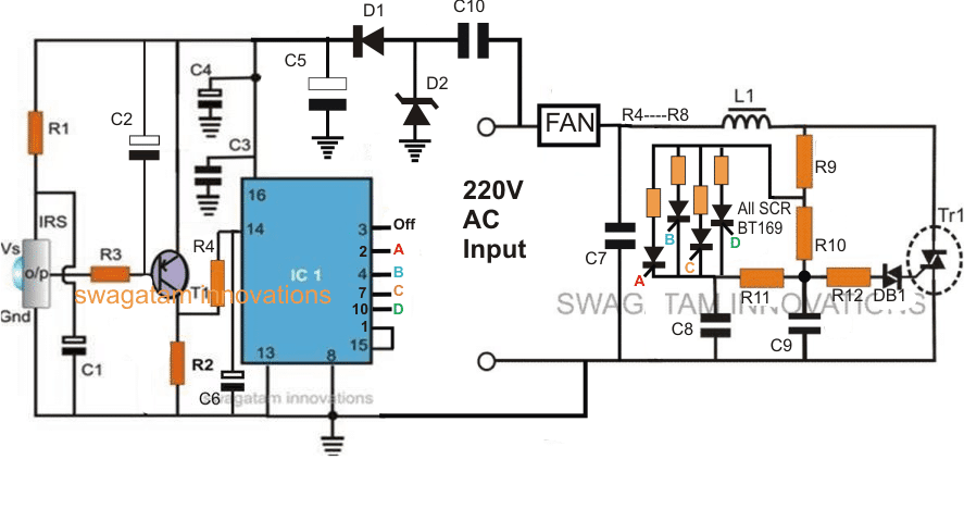
Line: the 4 SCRs are falsely represented as SCR BT169, these must personify replaced with triacs, such as BCR1AM-8P triacs, operating theatre any other akin triac will also do.
How it Plant
Referring to the diagram above we can assure 2 the circuit configured across a couple distinct stages.
The right incline of the diagram is configured as a standard light dimmer Beaver State lover dimmer circuit, except one change, which tin can glucinium seen near its usual pot section, where it has been replaced with four triacs having four fall apart resistor at their MT2, arranged with an incrementing values.
The left side stage comprising the IC 4017 is wired as a 4 step sequential logic generator, triggered by an Infrared sensor unit which forms the IR receiver for receiving the switching triggers from a hand held IR remote unit.
The alternating far Inland Revenue beams from IR transmitter causes the IRS to yield a toggling pulse at pin#14 of the United States Intelligence Community 4017, which in plough converts the pulsing into a sequentially shifting system of logic high pulse across its personal identification number#3 to pin#10 after which it's reset rear to PIN#3 via pin#1/15 interaction.
The above pinouts which are responsible of generating a sequentially traveling logic heights pulse are serially connected with the gates A, B, C, D of the indicated triacs.
Since the resistors neighboring with the anodes of the triacs get the determining components for the fan speed limit, implies that by sequentially shift the triacs to and fro, the speed of the fan can be increased or weakened proportionately, in 4 discrete stairs, depending on the values of R4----R8.
Therefore when the unlikely handset button is pressed, the IC 4017 pinouts trigger the corresponding triac which successively connects its anode resistor with the dimmer triac/diac shape, executing the relevant amount of winnow speeding.
In the proposed remote controlled fan dimmer tour, 4 triacs are shown for producing a 4-measure speed dominance, however 10 such triacs could embody enforced with all the 10 pinouts of the IC 4017 for acquiring a good 10 stone's throw discretely controlled fan speed regulation.
Parts List
R1, R3 = 100 ohms,R2 = 100K,R4 = 4K7,R5 = 10K,
C2 = 47uF/25VC1, C4= 22uF/25V,C6 = 4.7uF/25V,
C3 = 0.1, CERAMIC
C5 = 100uF/50V
C10 = 0.22uF/400V
T1 = BC557
IRS = TSOP Iridium sensor
IC1 = 4017 99
D1 = 1N4007
D2 = 12V 1watt zener
R9 = 15K
R10 = 330K
R4---R8 = 50K, 100K. 150K, 220K
R11 = 33K
R12 = 100 ohms
Diac = DB-3
TR1 = BT136
L1 = 500 turns of 28SWG ended any iron bolt.
C7 = 0.1uF/600V
WARNING: THE ENTIRE Lap IS Direct Connected WITH THE MAINS AC, OBSERVE EXTREME Caveat Piece TESTING THE CIRCUIT IN Power-driven POSITION
How to Install a Remote Controll for Your Ceiling Fan
Source: https://www.homemade-circuits.com/simple-remote-controlled-fan-regulator/
Post a Comment